Engineering · 12 min read
How to size a water booster station: a practical engineering guide.
A walk-through of flow, head, redundancy, and control decisions that decide whether a booster station runs quietly for decades — or fails at 2 a.m.
Sizing a water booster station is one of those engineering problems that looks simple on paper and gets complicated the moment a real distribution system is involved. At its core, the job comes down to two numbers: the peak design flow the station has to deliver and the total dynamic head it has to overcome at that flow. Everything else — pump count, motor horsepower, piping diameter, control strategy, building footprint, and electrical service — follows from those two figures. Get them right and the station will quietly do its job for decades. Get them wrong and you end up with cavitation, short cycling, blown seals, energy bills nobody can explain, and a phone that rings at 2 a.m.
Our engineering teams have specified booster stations for everything from 35-home rural co-ops to municipal pressure zones serving tens of thousands of residents. The process is the same in either case; only the scale changes. This article is the long-form version of that conversation — how we approach flow, head, redundancy, controls, and the field details that determine whether a station performs as designed once it is installed.
Start with peak demand, not average demand.
The single biggest sizing mistake we see is engineers anchoring on average day demand. Average day is useful for storage and treatment capacity, but it tells you almost nothing about what a booster station has to do. Booster stations live in the peak — peak hour, peak instantaneous, and the worst-case fire-flow event the local code authority cares about.
Start with the maximum day demand and apply a peaking factor to land on peak hour. For most small-to-medium systems, peak hour runs 1.5 to 3.5 times average day, with the larger multipliers showing up in smaller, more residential systems where morning and evening usage spikes are sharper. Then layer in fire-flow if the zone is fire-protected: 1,000 to 3,500 GPM depending on construction class and building occupancy, sustained for the duration the local code requires (commonly two hours).
Your design flow is whichever scenario is larger — peak hour domestic demand or peak domestic plus fire flow. In most pressure zones that handle both, fire flow drives the sizing. In zones served from elevated storage with separate fire pumps, peak hour usually wins. Document which scenario you sized against and why; the AHJ will ask, and the operator will be glad you wrote it down.
Build the system curve before you pick a pump.
Once you have a design flow, you need to know how much head the station has to add at that flow. Total dynamic head (TDH) is the sum of static lift, friction losses through the piping and fittings, and any pressure the downstream system requires at the boundary. Skipping any of these three components is how stations end up undersized or oversized.
Static lift is straightforward: the elevation difference between the suction source and the highest point the station needs to serve, plus the residual pressure required at that high point. If a hilltop home needs 40 PSI at the meter, that's roughly 92 feet of head you owe the homeowner before friction is even in the picture.
Friction loss is where engineers get sloppy. Plug the design flow into Hazen-Williams or Darcy-Weisbach for every significant pipe segment, every fitting, every valve. For long transmission mains, this dominates the head curve. We routinely see stations specified against a friction estimate that's 30% low because someone used a generic per-foot allowance instead of an actual hydraulic model.
Plot the resulting system curve from zero flow up to about 120% of design flow. The intersection of that curve with the pump curve is your duty point — and the shape of where they cross tells you almost everything about how the station will behave in real operation.
Pump count and redundancy: the N+1 rule.
Once you know the duty point, you can choose how to split the flow across pumps. The starting rule is N+1 redundancy: pick the smallest number of pumps that can handle peak design flow, then add one more of the same size as a backup. For a station that needs 1,500 GPM and you've picked 750 GPM pumps, that means two duty pumps plus one standby — three pumps total.
Splitting a station across multiple smaller pumps does several useful things. It improves turndown — a small system at low demand can run one pump at part-speed instead of cycling a single large pump on and off. It improves redundancy — losing one pump doesn't drop the station below design capacity. And it improves serviceability — you can pull one pump for rebuild without taking the station out of service.
There are limits. Splitting too far drives up cost, footprint, and electrical service size with diminishing returns. For most municipal duty points we land on two or three duty pumps plus a standby. Above 5,000 GPM, four-pump arrangements start to make sense; below 300 GPM, a single duty pump with an in-stock spare is often more cost-effective than a permanent standby on the manifold.
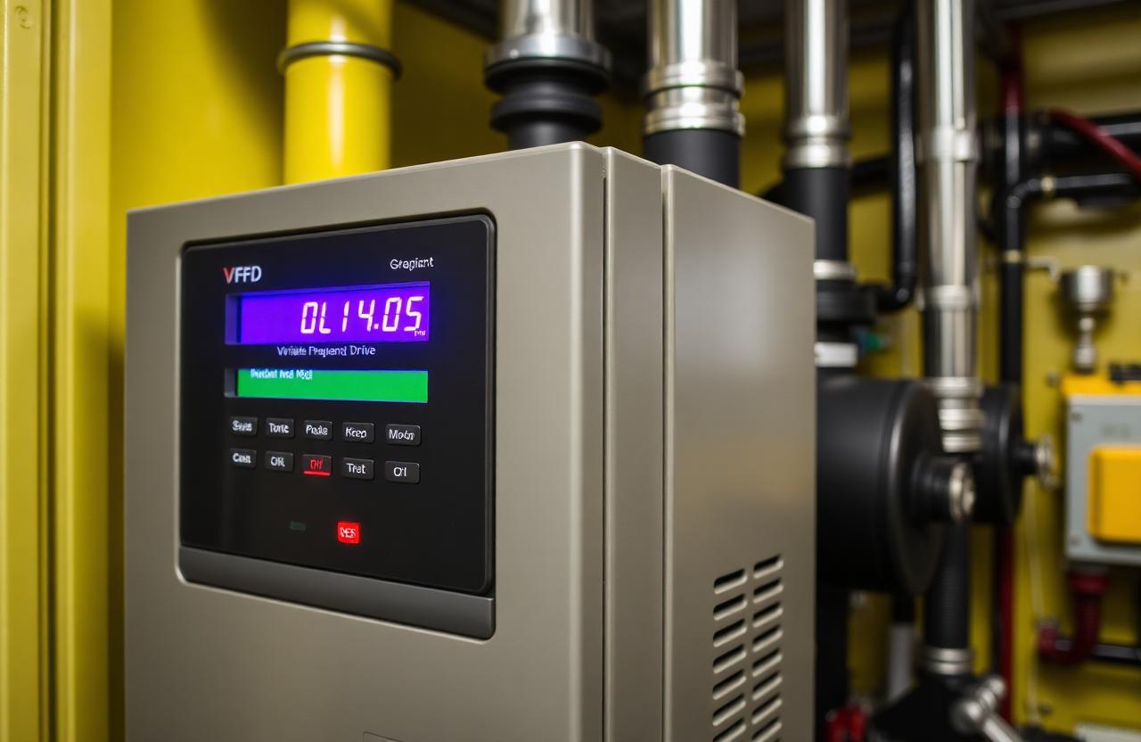
VFD or constant speed? It depends on the demand pattern.
Variable frequency drives get pitched as the universal upgrade, but they only earn their cost back on systems with strongly variable demand. A station feeding a residential pressure zone with sharp morning and evening peaks and long quiet stretches at night is a clear VFD candidate — the drive lets you match output to demand instead of cycling pumps on and off all day.
A station feeding a transmission main that runs near full flow most of the day is a different animal. There, constant-speed pumps with soft starters often outperform VFDs on first cost, efficiency, and reliability. The drive overhead — switching losses, harmonic mitigation, motor derating — eats into savings when the duty cycle stays flat.
The rule of thumb we use: pull telemetry from a comparable site for at least a few weeks. If the load spends more than 40% of the year below 90% of best-efficiency-point flow, VFDs typically book a three-year-or-better payback. If it doesn't, hold the line on constant speed and put the savings into better instrumentation.
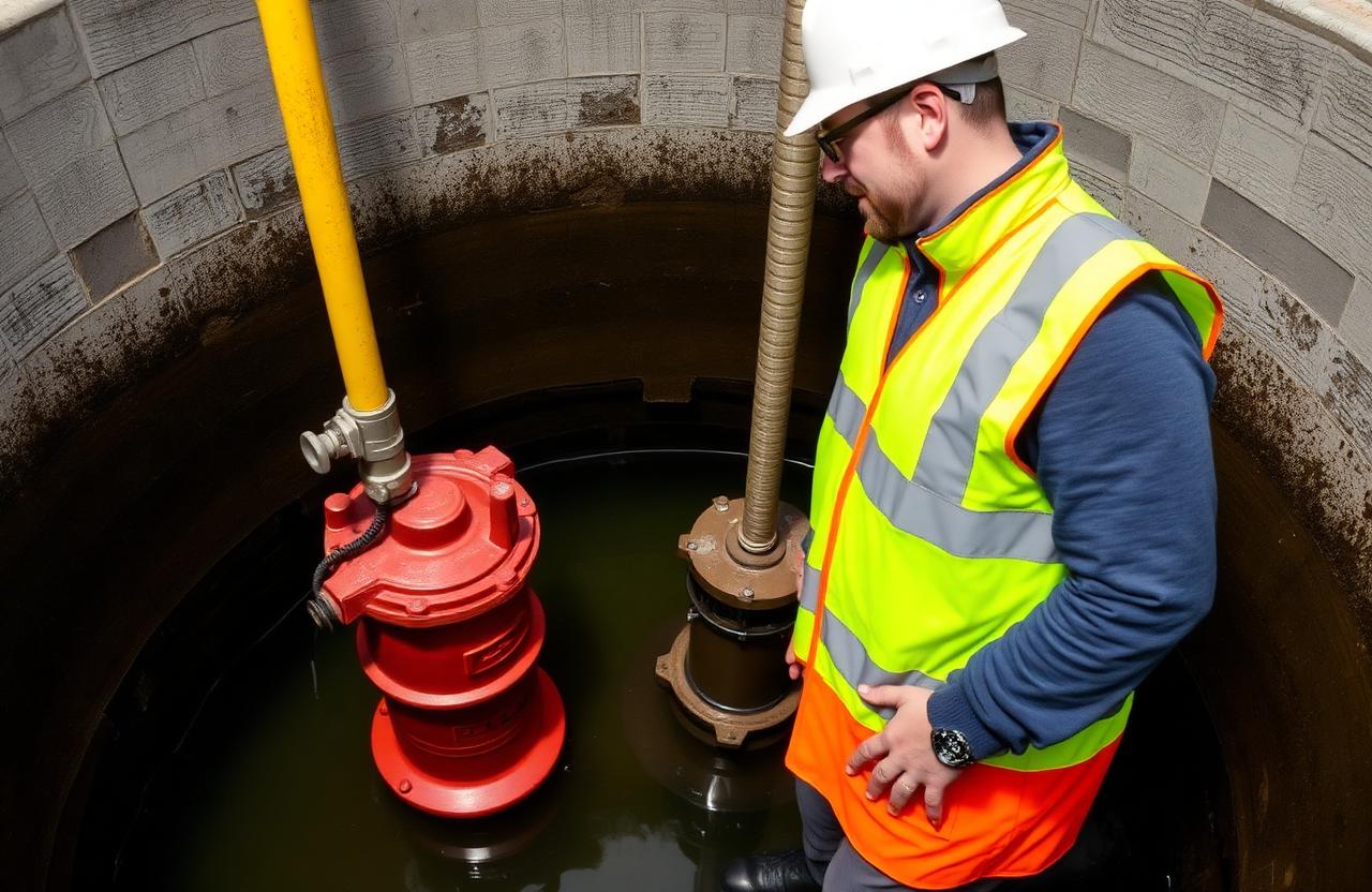
Don't forget NPSH and suction-side conditions.
Net positive suction head (NPSH) is the variable that quietly kills more booster stations than any other. Every pump curve specifies an NPSH required (NPSHr) at each flow. Your job is to make sure NPSH available (NPSHa) at the suction flange exceeds NPSHr by a comfortable margin — typically 3 to 5 feet — across the full operating range.
NPSHa is set by suction-side static pressure, friction losses upstream of the pump, vapor pressure of the fluid at operating temperature, and atmospheric pressure at elevation. Hot water, high altitudes, long suction lines, and undersized inlet piping all eat into NPSHa fast. Cavitation from low NPSH chews up impellers, hammers seals, and shortens motor life without ever tripping a single alarm.
A simple check: at design flow, walk through the suction side from source to pump flange and tally every foot of friction. Then compute NPSHa using the standard formula and compare against the pump's NPSHr at that flow. If margin is under 3 feet, redesign the suction piping before you commit to a pump. It is almost always cheaper than the rebuilds you'll otherwise be doing every two years.
Controls strategy: match the duty pattern.
Control strategy is where booster stations stop being a hydraulics problem and start being an operations problem. The right strategy depends on whether the station is feeding a hydropneumatic tank, an elevated reservoir, or directly into a pressure zone.
Hydropneumatic systems lend themselves to pressure-switch or PID control on discharge pressure, with VFDs ramping speed to hold a setpoint. Elevated storage typically uses level control — pumps stage on as the tank level drops and off as it recovers. Direct-pressure zones often run on discharge pressure setpoint with lead/lag rotation to even out wear across the fleet.
Whatever the strategy, build in the basics: lead/lag rotation by run hours, automatic standby promotion on fault, low-suction-pressure cutout to protect against dry running, high-discharge-pressure trip, and a clean SCADA dashboard that shows the operator what each pump is doing and why. Operators who can see the system trust it. Operators who can't, override it.
Field details that decide success.
Two stations with identical hydraulic designs can perform very differently based on installation details that rarely show up on the one-line drawing. A few that matter more than they should.
Suction piping length, alignment, and reducers: long horizontal runs with eccentric reducers installed flat-side-down trap air at the pump suction. Use eccentric reducers flat-side-up on horizontal pumps and keep straight suction pipe of at least five pipe diameters before the flange.
Vibration isolation: rigid pipe connections transmit pump vibration into the building structure and back into the pumps. Use flexible connectors at the suction and discharge of each pump, and isolate the pump base from the slab with proper inertia bases or spring isolators on larger units.
Surge control: every time a pump starts or stops, the system experiences a pressure transient. On long discharge lines or systems with check valves, that transient can ring at amplitudes that crack fittings and blow gaskets. A surge analysis on any station above about 1,000 GPM on a long main is cheap insurance.
Operator access: the difference between a 20-minute seal replacement and a four-hour ordeal is whether someone left room to swing a wrench. Mock the maintenance walkthrough on the drawing before you sign it.
What good sizing actually looks like.
When sizing has been done well, the station hits its design flow at a duty point that's within 10% of best efficiency, has clear redundancy headroom for any single-pump failure, and has a control strategy that operators understand without a manual. Energy use is predictable, alarms are rare, and maintenance is scheduled rather than reactive.
When sizing has been done poorly — usually because someone skipped the system curve, ignored fire flow, or undersized the suction — the same station limps along with pumps running far off BEP, cycling constantly, drinking power, and burning seals. The fix is rarely to swap pumps; the fix is to redo the hydraulic study and rebuild the manifold.
If you're early enough in a project to influence the sizing, this is the article we'd hand you. If you're already past it and the station isn't behaving, the audit usually takes less than a week and the changes pay for themselves within the year. Either way, the underlying engineering is the same — and worth doing carefully.